Solar Panel Fire Risk: Comprehensive Safety Guide for PV Installations
- Apr 23
- 10 min read
Updated: Apr 24
Photovoltaic systems installed on pitched roofs present specific fire safety considerations that differ markedly from other electrical installations. When European insurers began excluding unprotected arrays from standard commercial property policies in 2024, the solar industry confronted a question many installers and EPCs had dismissed as theoretical: what conditions actually elevate solar panel fire risk, and how do we document their mitigation?
This guide examines the evidence base for fire hazards in pitched-roof PV installations, focusing on preventable risks arising from biological contamination, installation defects, and deferred maintenance. Drawing from incident data, laboratory testing standards, and field observations across DACH and Mediterranean markets, we identify where risk concentrates and what technical measures reduce it.
Why Fire Risk Differs in Photovoltaic Systems
Unlike AC grid infrastructure, photovoltaic arrays operate under continuous DC voltage whenever the sun is above the horizon. A 20 kWp residential system generates 600-800 VDC under load — voltage levels at which carbon tracking, arc faults, and thermal runaway develop rapidly once insulation integrity is compromised.
Fire incidents in PV systems rarely originate from the solar cells themselves. Manufacturing defects in bypass diodes, poorly crimped MC4 connectors, and cable insulation degradation account for the majority of documented cases. The European Commission Joint Research Centre's 2019 technical report on PV fire safety identified three primary failure modes: DC arcing between conductors, module-level overheating from bypass diode failure, and ignition of combustible debris accumulated under the array perimeter.
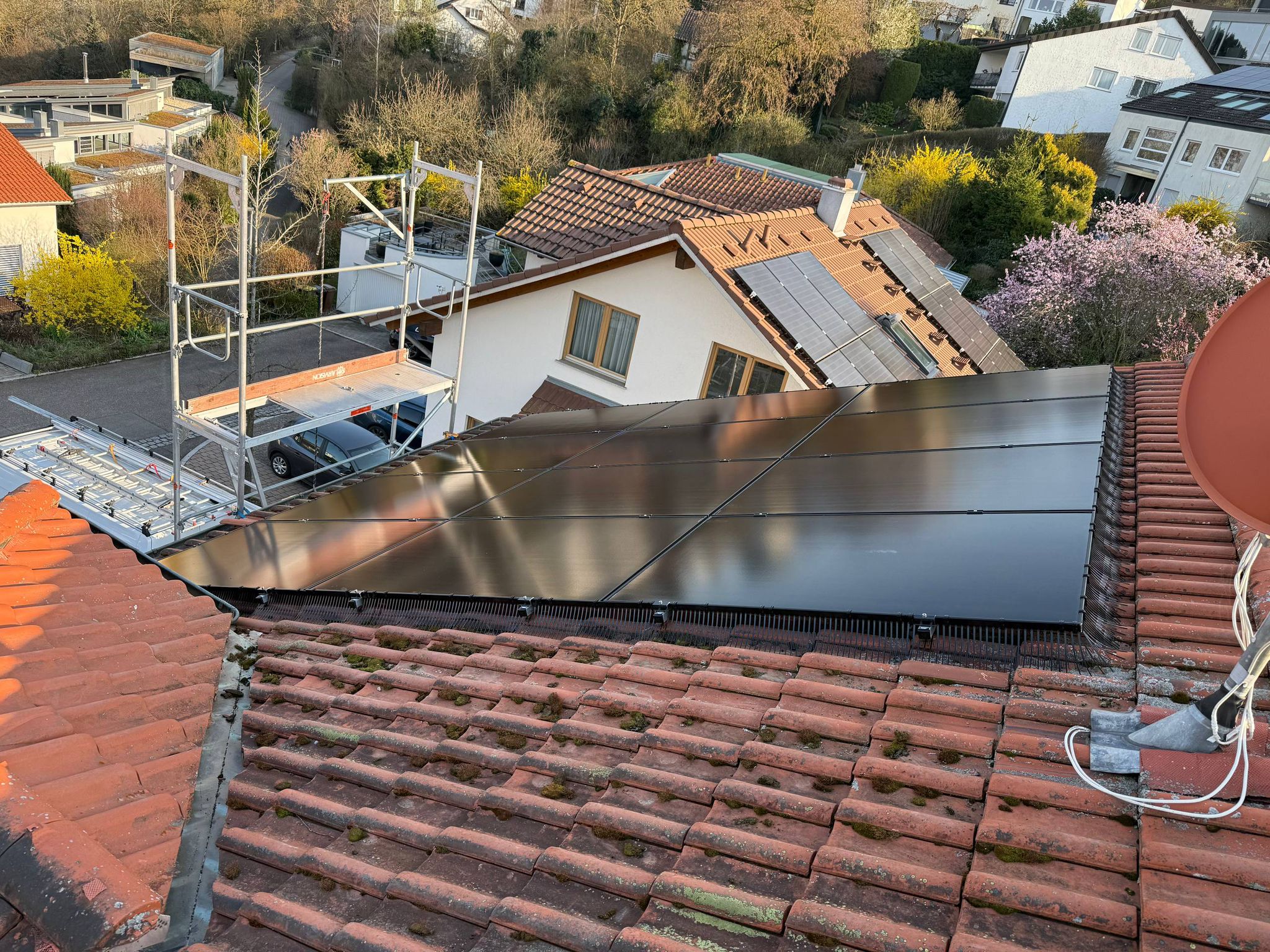
What makes pitched-roof installations particularly vulnerable is the gap between the module underside and the roof membrane — typically 80-150 mm depending on rail height and module tilt. This cavity becomes a sheltered microclimate where biological activity, wind-blown debris, and moisture accumulate unobserved until a maintenance inspection reveals the extent of contamination.
Bird Activity as a Fire Catalyst
The correlation between bird nesting and fire incidents in roof-mounted PV systems is well-documented but not widely understood. Birds do not ignite fires directly; rather, they create conditions that accelerate known electrical failure modes.
Nesting Material and Flammability
Pigeons, sparrows, and starlings build nests from dry twigs, feathers, moss, and in urban environments, paper and plastic fragments scavenged from waste bins. Laboratory flammability testing conducted by TÜV Rheinland in 2021 demonstrated that dried pigeon nesting material ignites at temperatures as low as 210°C — well below the thermal output of a localised DC arc fault, which can exceed 3000°C at the point of discharge.
Once nesting material is present in the module-to-roof gap, the array becomes a multi-point ignition risk. A single compromised cable anywhere along the string can ignite accumulated debris, which then spreads flame horizontally beneath the modules faster than a roof-level fire would propagate in the open.
Cable Abrasion and Insulation Failure
Birds do not chew through PV cables in the manner rodents do, but their movement patterns cause mechanical abrasion. As adults enter and exit nests, they repeatedly brush past DC cables suspended in the perimeter gap. Over months, this contact wears through the UV-resistant sheath and exposes the copper conductor.
Inspections of arrays with active bird nesting typically reveal 2-5 mm sections of exposed conductor within the first two nesting seasons. Once the conductor is exposed, moisture ingress from rain or morning condensation creates a conductive path to the grounded aluminium rail. The resulting leakage current accelerates corrosion, increases string resistance, and under certain fault conditions, initiates a ground fault arc.
DC Arc Faults and Solar Panel Fire Risk: The Primary Ignition Mechanism
A DC arc fault occurs when current jumps an air gap between two conductors or between a conductor and ground. Unlike AC arcs which self-extinguish at the zero-crossing point of the sine wave, DC arcs sustain continuously as long as sufficient voltage and current are present.
Where Arc Faults Develop
In pitched-roof PV installations, arc faults most commonly develop at:
1. MC4 connector interfaces — inadequate crimping or water ingress corrodes the contact surface, increasing resistance until localised heating melts the connector housing and separates the conductors under tension.
2. Cable entry points at junction boxes — inadequate strain relief allows cable movement from thermal expansion/contraction, gradually working the conductor loose from the terminal block.
3. Points of mechanical damage — where cables cross sharp edges (rail ends, roof brackets) or where bird activity has abraded the insulation.
4. Module frame edges — if the cable is routed too close to the aluminium frame without adequate clearance, vibration from wind loading can wear through the insulation over years.
Why Detection Is Difficult
Standard overcurrent protection devices (fuses, circuit breakers) do not reliably detect series arc faults because the fault current remains within the normal operating range of the string. A 10 A string might arc at 8 A — below the trip threshold of a 15 A fuse, yet sufficient to sustain a 3000°C plasma arc.
Arc-fault circuit interrupters (AFCIs) designed for DC strings detect the characteristic high-frequency noise signature of arcing and interrupt the circuit within milliseconds. However, AFCI adoption in European residential and small-commercial PV installations remains below 15 per cent, per data from SolarPower Europe's 2025 market report. The devices add material cost, require string-level installation, and in some inverter topologies introduce compatibility issues with maximum power point tracking.
For systems without AFCI protection, arc faults progress undetected until smoke is visible or a thermal camera inspection reveals a hot spot.
Ventilation Blockage and Thermal Runaway Risk
Photovoltaic modules are rated for operation at a specific maximum temperature, typically 85°C at the back-surface laminate. Exceeding this threshold accelerates degradation of the EVA encapsulant, solder bond fatigue, and in extreme cases, delamination of the front glass.

Bird nests and accumulated debris under the module perimeter obstruct the natural convective airflow that cools the array. On a summer day with 35°C ambient temperature and 1000 W/m² irradiance, a well-ventilated module operates at 60-65°C back-surface temperature. Block that airflow with nesting material, and the same module can reach 80-90°C.
At these elevated temperatures, bypass diodes — which already dissipate significant heat under partial shading conditions — approach their absolute maximum rated junction temperature. Bypass diode failure presents in two modes: short-circuit (the module continues operating with reduced output) or open-circuit (the entire string voltage drops). In rare cases involving counterfeit or substandard diodes, thermal runaway can ignite the diode potting compound inside the junction box.
Debris Accumulation: The Overlooked Ignition Source
Moss, leaves, plastic sheeting fragments, and windblown paper accumulate in the module-to-roof gap over time, particularly on arrays installed near deciduous trees or on commercial rooftops adjacent to ventilation exhausts. Unlike bird nesting material, this debris often goes unnoticed during visual ground-level inspections because it settles flat against the roof membrane.
Dry organic debris has similar flammability characteristics to nesting material. A controlled ignition test conducted by Fraunhofer ISE in 2020 demonstrated that a 5 mm layer of dry moss, when subjected to a 400°C heat source (simulating a localised cable fault), propagated flame across a 2 m² test surface within 90 seconds.
The risk compounds when debris traps moisture against the roof membrane. Prolonged moisture exposure degrades bitumen-based waterproofing layers, and in metal roofing applications, accelerates corrosion of fasteners and seams. A roof penetration failure introduces water into the building envelope, but more critically for fire risk, it creates a conductive path between the PV system earthing conductor and the building structure.
Insurance and Regulatory Implications
European commercial property insurers have responded to rising PV fire claims by revising coverage terms. As of 2024, several major underwriters in Germany, Italy, and France now exclude fire damage claims on PV systems unless the installation meets specific risk-mitigation criteria:
- Annual thermographic inspection records - Documentation of perimeter protection measures (bird exclusion, debris barriers) - Confirmation that DC cabling routes avoid contact with flammable materials - Evidence of installer certification to national standards (DIN VDE 0100-712 in Germany, NF C 15-100 in France)
For EPCs managing commercial and agricultural pitched-roof projects in the 100 kWp to 1 MWp range, these exclusions materially affect project bankability. Lenders financing installations under power purchase agreements require proof of insurable risk for the full contract term — typically 15-20 years. An uninsurable fire risk forces the project sponsor to either self-insure (requiring capital reserves) or accept higher insurance premiums that erode the project IRR.
From a regulatory perspective, the revised IEC 61730 standard (Edition 2.1, published 2023) now requires PV modules to pass an extended fire-propagation test when intended for rooftop installation in fire-class C or higher buildings. This test simulates ignition from an external source beneath the module and measures time-to-flame-spread and smoke production. Modules passing this test receive an "F-rating" which several EU member states now reference in building codes for commercial rooftop installations.
Mitigation Hierarchy: Design, Installation, and Maintenance
Reducing solar panel fire risk requires intervention at three stages: system design, installation execution, and operational maintenance.
Design-Phase Decisions
At the design stage, EPC teams and system specifiers should:
- Route DC cabling away from combustible building materials. Avoid running cables through wooden soffits, across timber roof members, or in contact with spray-foam insulation. Use metal conduit or cable trays with fire-resistant coating where routing through enclosed spaces is unavoidable.
- Specify AFCI-equipped inverters for systems above 10 kWp. The incremental cost per watt is minimal, and the risk reduction is substantial, particularly in installations where regular maintenance is unlikely.
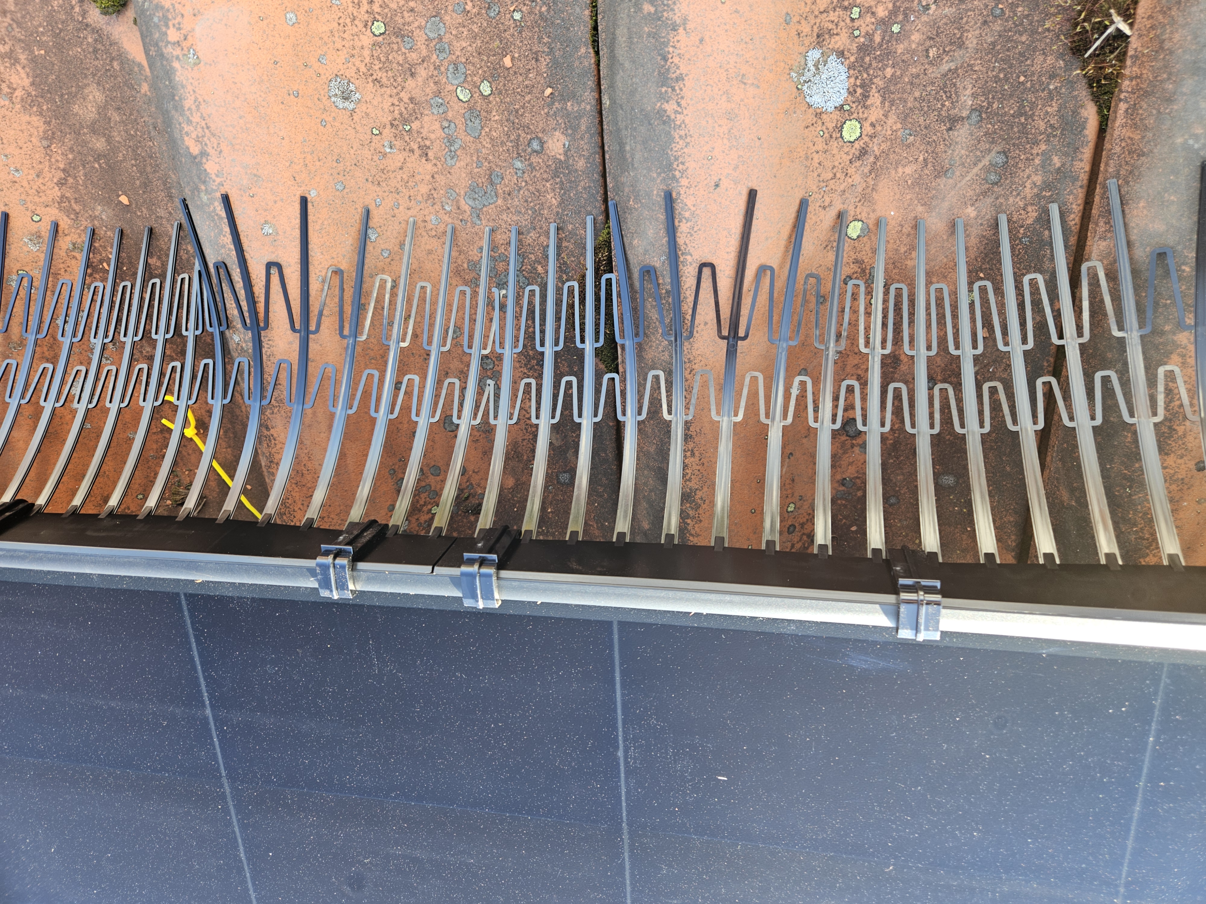
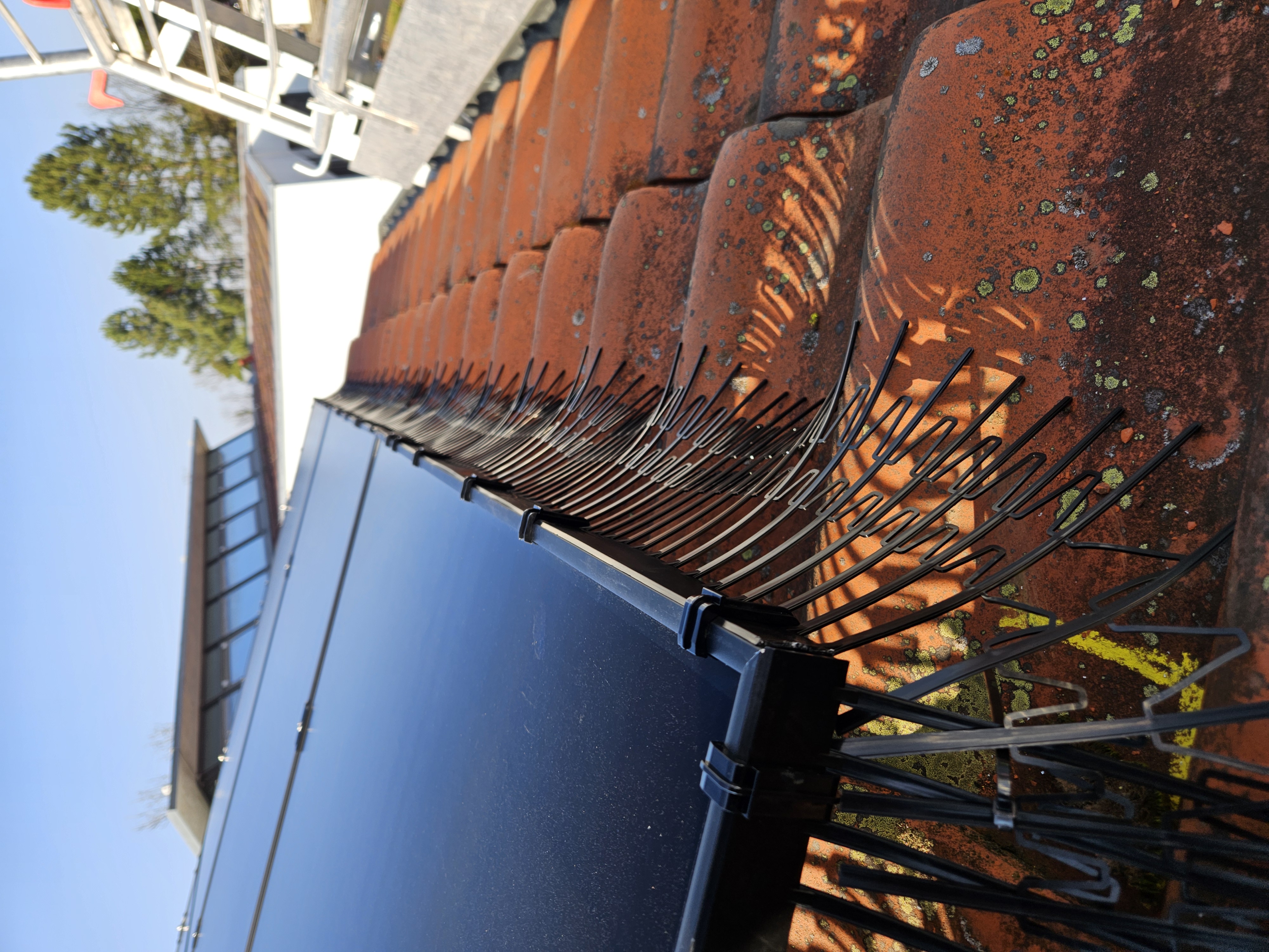
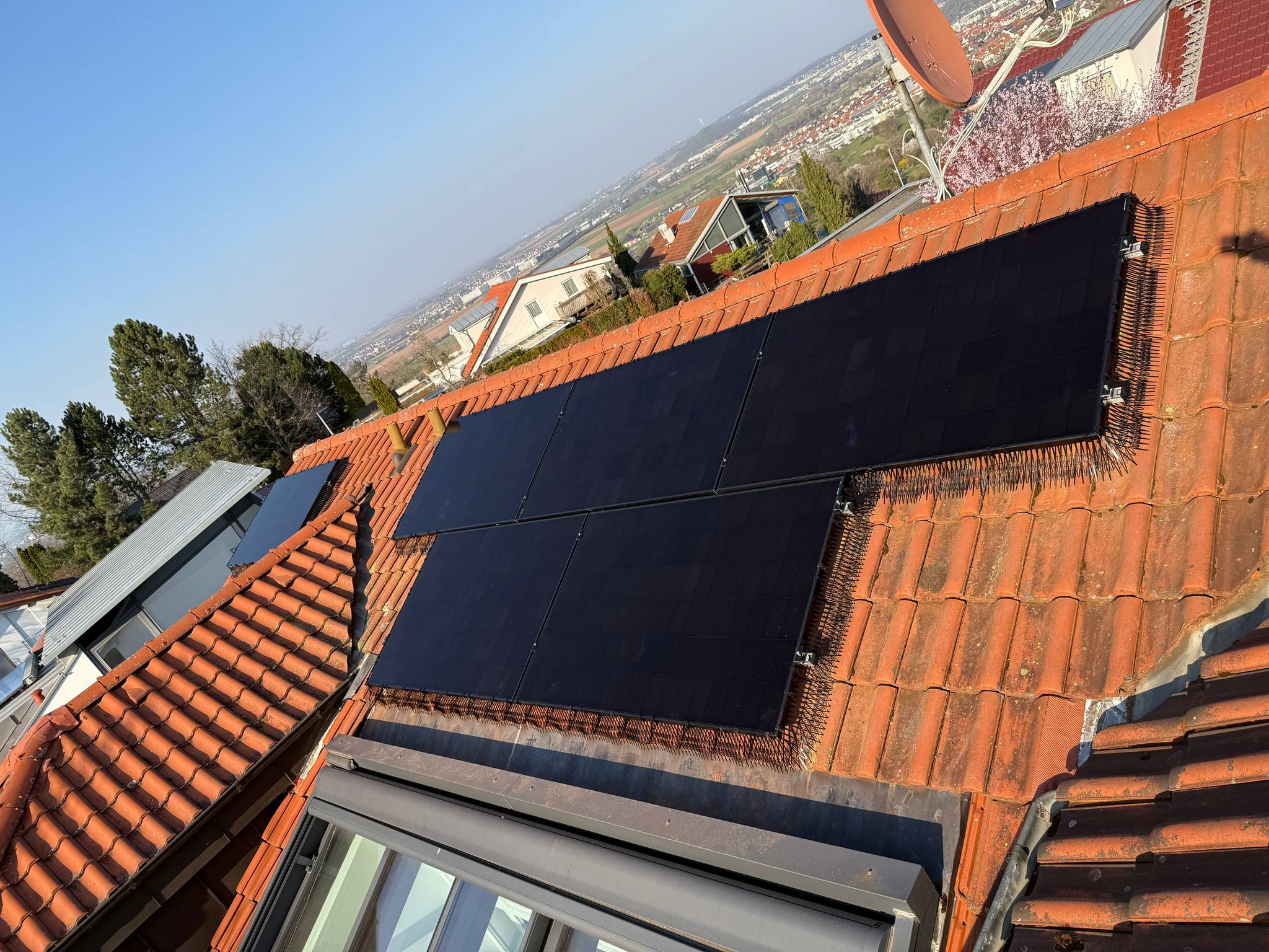
- Include perimeter protection in the initial bill of materials. Retrofit bird exclusion is more expensive and less effective than purpose-designed systems installed during commissioning. Physical barriers that prevent access to the module-to-roof gap eliminate both nesting activity and debris accumulation.
- Ensure adequate module-to-roof clearance for ventilation. Minimum clearance depends on module dimensions and local climate, but best practice is 100 mm for residential installations and 120-150 mm for commercial arrays where debris loading is higher.
Installation-Phase Quality Control
During installation, field crews should:
- Inspect every MC4 connector crimp with a pull test. A properly crimped connector requires more than 50 N of force to separate — if it pulls apart by hand, remake the connection.
- Secure cables with UV-resistant cable ties at 300 mm intervals. Unsecured cables sag, vibrate in wind, and contact sharp edges. Proper cable management extends insulation life by a decade or more.
- Photograph the underside of the array before final panel installation. Document that the roof surface is clear of debris and that no combustible materials are present in the gap. This photographic record becomes critical evidence for insurance inspections and commissioning audits.
- Verify earthing continuity across the entire rail structure. Measure resistance between the furthest module frame and the main earthing terminal — it should be below 0.1 Ω. High resistance indicates a poor bond, which increases the likelihood of arcing at that joint.
Maintenance and Inspection Protocols
Operational PV systems on pitched roofs should be inspected annually for fire risk indicators:
- Thermographic inspection under load. Conduct the inspection on a clear day with irradiance above 700 W/m² to ensure modules are generating sufficient current to reveal resistive faults. Hot spots above 15°C differential from adjacent cells indicate a developing fault.
- Visual inspection of the perimeter gap. Use a mobile phone camera or inspection mirror to photograph beneath the array edge. Look for nesting material, debris, and cable abrasion marks on insulation.
- Insulation resistance testing of DC strings. With the array disconnected and isolated, measure insulation resistance between the positive/negative DC bus and ground. A reading below 1 MΩ suggests moisture ingress or insulation damage and warrants further investigation.
- Review inverter fault logs. Modern string inverters log ground-fault events, isolation faults, and string current imbalances. A pattern of transient ground faults often precedes a persistent arc fault by weeks or months.
Pitched-Roof Specifics: Why Geometry Matters
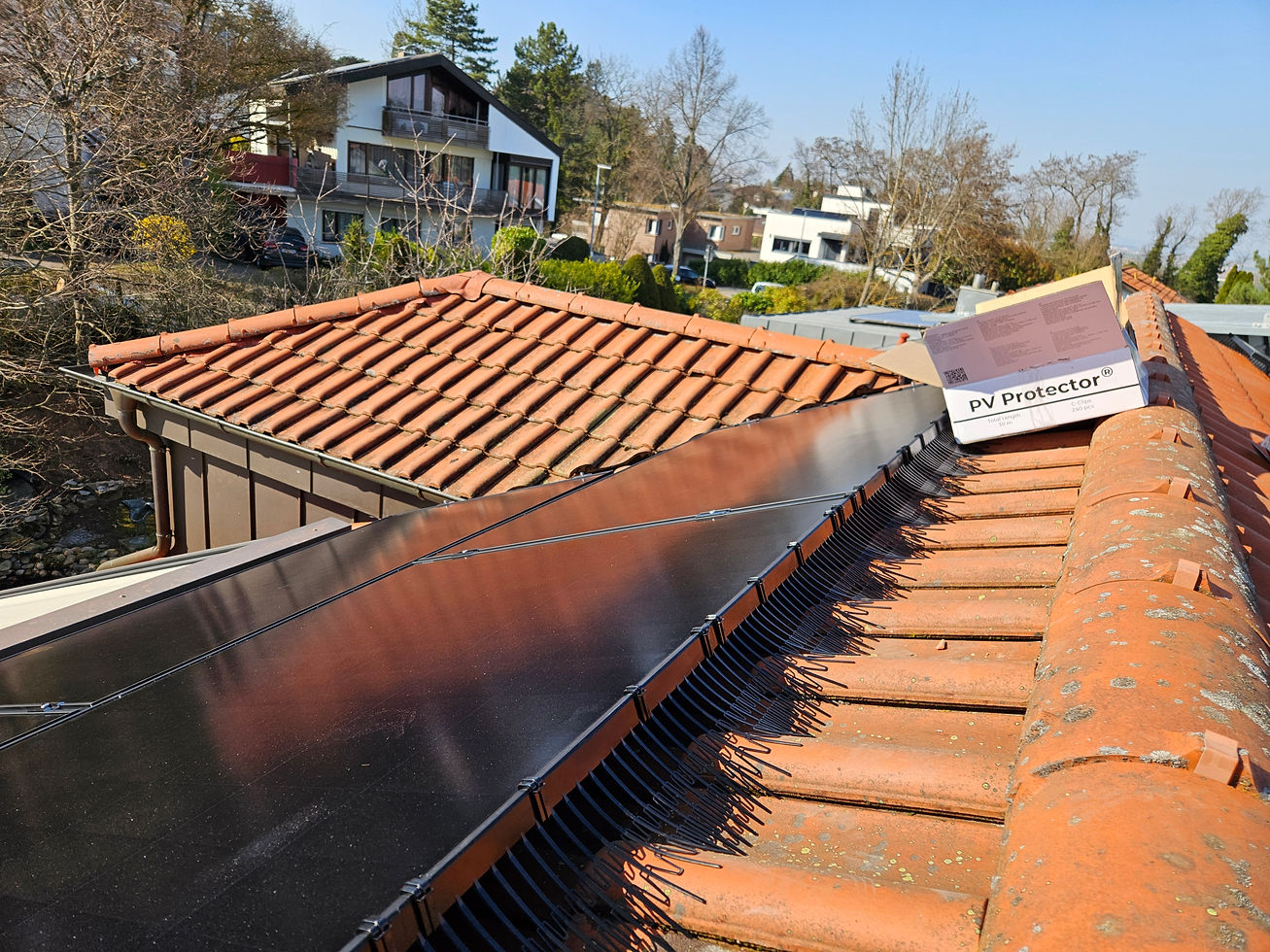
PV Protector® is engineered specifically for pitched-roof installations where a defined lower module edge creates a bird-accessible cavity. The product does not apply to flat-roof ballasted systems, ground-mount arrays, or agrivoltaic installations where the geometry differs fundamentally.
On flat roofs, ballasted tilt-rack systems elevate modules 200-600 mm above the roof membrane on structural supports that leave large open areas beneath the array. Birds can access these spaces from multiple angles, and physical perimeter barriers do not provide effective exclusion. These installations require different risk-mitigation approaches — typically netting suspended beneath the entire array or periodic manual nest removal.
Ground-mount and utility-scale arrays present negligible fire risk from bird activity because the array is elevated well above ground vegetation, and any arc fault or thermal event occurs in open air with no enclosed combustible materials. Regulatory focus for these installations centres on vegetation management and clearance to property boundaries, not bird exclusion.
When specifying fire-risk mitigation for a project, confirm the installation type first. Pitched-roof residential and commercial arrays — where modules are mounted close to a combustible or semi-combustible roof surface — represent the specific geometry where perimeter protection reduces fire risk.
Fire Safety Checklist for Installers and EPCs
Use this checklist during design review, commissioning, and annual inspections:
Design & Procurement: - [ ] DC cable routing avoids contact with combustible materials - [ ] AFCI protection specified for strings above 10 kWp - [ ] Perimeter protection system included in BOM - [ ] Module-to-roof clearance meets manufacturer ventilation requirements
Installation: - [ ] All MC4 connectors pass pull test (>50 N) - [ ] Cables secured at 300 mm intervals with UV-resistant ties - [ ] Photographs document clean roof surface before final module placement - [ ] Earthing resistance <0.1 Ω across rail structure
Commissioning: - [ ] Thermographic scan shows no hot spots >10°C differential - [ ] Insulation resistance >1 MΩ on all strings - [ ] Inverter logs clear of ground-fault warnings - [ ] Perimeter protection installed with no gaps >10 mm
Annual Maintenance: - [ ] Thermographic inspection under load - [ ] Visual check of perimeter gap for nesting/debris - [ ] Insulation resistance retest - [ ] Inverter fault log review
Evidence Base and Further Reading
The data supporting this guide derives from multiple sources:
- The European Commission Joint Research Centre's 2019 Technical Report on PV System Fire Safety documents failure modes and testing protocols for module-level fire resistance.
- TÜV Rheinland's flammability testing of organic materials commonly found in roof-mounted PV installations provides ignition temperature thresholds.
- Fraunhofer ISE's controlled ignition tests demonstrate flame propagation rates in debris-contaminated installations.
- SolarPower Europe's annual market reports track AFCI adoption rates and insurance industry responses to PV fire claims.
- IEC 61730 Edition 2.1 (2023) establishes the current international standard for module fire safety testing and F-rating classification.
For a comprehensive understanding of international best practices, consult the International Renewable Energy Agency's updated guidelines on PV system safety available here.
What EPCs and Installers Should Do Next
If you manage pitched-roof PV installations in commercial or agricultural settings, review your current fire-risk mitigation protocols against the checklist above. Particular attention should be given to:
1. Insurance compliance — contact your underwriter to confirm whether your current installation practices meet their revised coverage requirements.
2. Retrofit assessment — for systems already in operation, schedule thermographic and visual inspections to identify arrays with elevated risk profiles (visible nesting, debris, or cable damage).
3. Specification updates — revise your standard bill of materials to include perimeter protection and AFCI as default line items, not optional upgrades.
Fire risk in photovoltaic systems is manageable through informed design, disciplined installation, and regular maintenance. The systems that fail are those where risk factors accumulate unobserved — where nesting goes unchecked, where cables are poorly secured, where thermographic inspections are deferred.
About PV Protector®
PV Protector® is a physical exclusion system for pitched-roof photovoltaic installations, designed to prevent bird access to the module-to-roof cavity. The system uses UV-stabilised HDPE perimeter segments and tool-free C-Clip mounting compatible with 30, 35, and 40 mm module frames. Manufactured by Pyramidi GmbH, Leonberg, Germany, with a 10-year material warranty.

Comments